What Is a Live-Shaft Conveyor Roller?
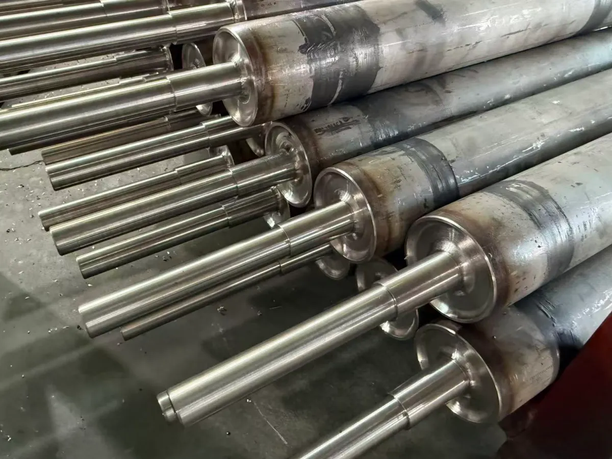
A live-shaft conveyor roller does not contain the pressed-in bearings normally found inside a standard gravity roller. Its tube, end plates, and shaft journals form one rotating assembly.
The machined journals rotate with the roller and run in external bearing units mounted on the customer’s machine or conveyor frame.
No bearings are installed inside the roller body. The external bearing arrangement must match the journal diameter, bearing-seat tolerance, shoulders, and mounting design specified in the customer drawing.
Two welded constructions are commonly manufactured:
- Two independent shaft journals connected to the roller through welded end plates
- One full through-shaft connected to the tube through welded end plates
Load path:
roller shell → end plates → welded joints → shaft journals → external bearings → machine frame
Materials Used in LEEV Live-Shaft Rollers
Material selection follows the customer drawing, operating environment, load conditions, and required surface finish. LEEV manufactures both carbon-steel and stainless steel live-shaft roller configurations.
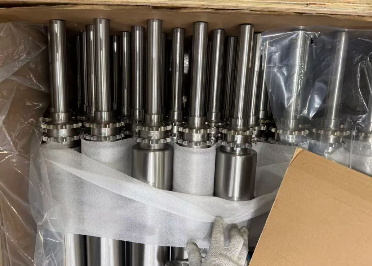
In a common carbon-steel construction, the roller tube and shaft are made from Q235 steel, while the welded end plates and drive sprockets are commonly made from Chinese grade 45 medium-carbon steel.
- Q235 tube and shaft for common carbon-steel constructions
- Chinese grade 45 steel for common end plates and drive sprockets
- Full 304 stainless steel construction for the tube, shafts, end plates, and sprockets
- Other material combinations manufactured according to the customer drawing
Drawing requirement:
the exact material grade, heat-treatment condition, and component combination should be stated on the customer drawing.
A Live-Shaft Roller Is Not the Same as a Live Roller Conveyor
The two phrases sound similar, but they describe different equipment concepts. One identifies how an individual roller and its shaft rotate; the other identifies a powered conveyor system.
When Is a Live-Shaft Roller Used?
A live-shaft roller is generally selected when the machine requires external bearings, a rigid connection between the roller body and shaft journals, or custom-machined drive and mounting features. The final construction should be determined from the customer’s drawing, load conditions, operating speed, bearing arrangement, and installation space.
if the component drives, redirects, or tensions a conveyor belt, a pulley or conveyor drum may be the more accurate term. If it supports products and its shaft journals rotate in external bearings, live-shaft conveyor roller is generally clearer.
Why Are the Shaft Journals Machined After Welding?
The shaft ends can be rough-machined before fabrication, but welding introduces heat and shrinkage. Even when every individual component is within tolerance, the completed weldment can move slightly as it cools.
- Unequal end-plate position
- Tube-end squareness
- Variation in the weld gap
- Uneven heat input around the circumference
- Different shrinkage at the two ends
- Fixture error
- Distortion in a long or thin-walled tube
If the bearing seats are finished to final size before welding, these changes can leave the two journals on slightly different axes. Installing external bearings on misaligned journals forces the bearing units and frame to compensate for the error.
Post-weld machining addresses this problem. The completed roller is set up from a controlled datum, and the functional journal surfaces are finish-turned after the welded assembly has stabilized. Depending on the drawing, machining may include:
- Bearing-seat diameters
- Shaft shoulders
- End faces
- External or internal threads
- Retaining-ring grooves
- Coupling diameters
- Drive-side locating features
How a Welded Live-Shaft Roller Is Manufactured
Manufacturing a welded live-shaft roller involves more than joining a tube, end plates, and shaft journals. The process includes drawing review, component preparation, positioning, circumferential welding, natural cooling, post-weld machining, surface finishing, and final inspection. The sequence is selected to establish the required relationship between the roller shell and both rotating shaft journals.
1Review the Drawing and Operating Conditions
The manufacturing route starts with the required function, not with the weld. The customer drawing and inquiry should define:
- Roller outside diameter and wall thickness
- Roller face length and overall length
- Journal diameters, lengths, shoulders, and threads
- External bearing model or required bearing bore
- Load per roller and load distribution
- Operating speed and duty cycle
- Driven or non-driven function
- Keyway, sprocket, pulley, or coupling details
- Surface treatment or coating
- Temperature, dust, moisture, chemicals, and washdown conditions
The external bearing arrangement is especially important because its bore, width, locking method, and mounting position determine the required shaft-journal geometry.
2Prepare the Tube, End Plates, and Shaft Blanks
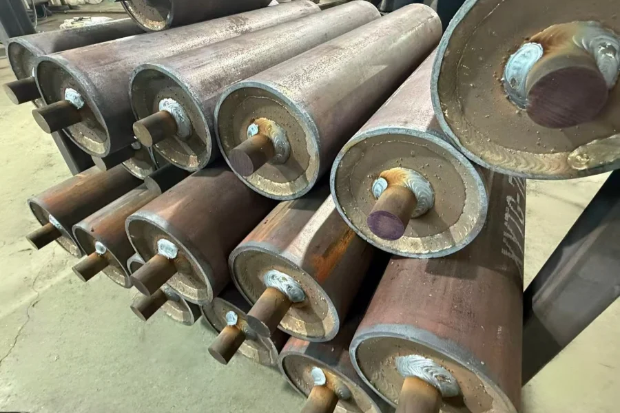
The roller tube is cut to the drawing length, and its ends are prepared for the end plates. The roller may use two independent shaft journals or one full through-shaft passing through the tube and connected to the end plates.
In a typical carbon-steel construction, the tube and shaft are made from Q235 steel, while the end plates and drive sprockets are commonly made from Chinese grade 45 medium-carbon steel.
The shaft blanks may be rough-machined before assembly, but sufficient material is retained on the functional journal surfaces for finish turning after welding.
3Position and Weld the Assembly
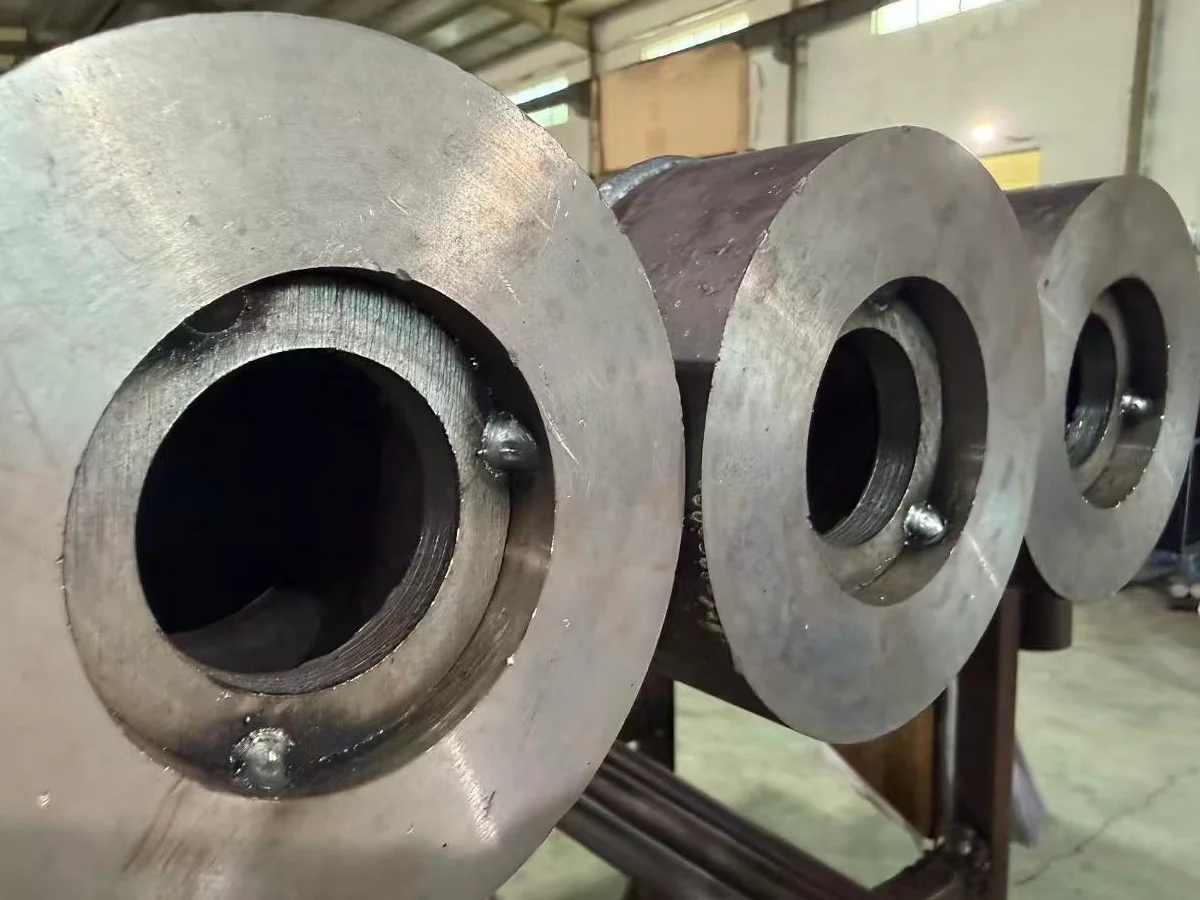
The tube, end plates, and shaft components are positioned according to the drawing. Tack welds hold the components in place before the circumferential welds are completed.
Depending on the material, wall thickness, joint design, and customer requirements, production may use MAG welding, TIG welding, or laser welding. After tack positioning, an automatic circumferential welding machine can be used to produce a consistent weld around the roller end.
4Allow the Welded Roller to Cool Naturally
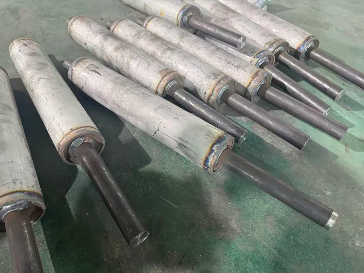
Welding introduces localized heat and shrinkage into the roller assembly. The completed weldment is therefore allowed to cool naturally before final machining.
This allows the welded structure to stabilize before the bearing seats, shoulders, and other functional journal surfaces are turned to their final dimensions.
5Finish-Turn the Shaft Journals
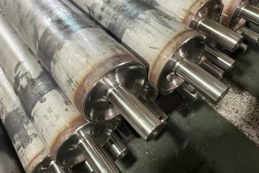
After cooling, the welded roller is mounted on a conventional lathe or CNC lathe. The final machining operation establishes the functional shaft-journal surfaces from the completed welded assembly.
Depending on the customer drawing, post-weld turning may include:
- Bearing-seat diameters
- Shaft shoulders and locating faces
- Shaft-end diameters
- Threads, grooves, and retention features
If machining both ends requires a second setup, the roller runout is measured and controlled during the first setup before the opposite end is machined.
6Machine the Drive and Retention Features
Keyways, flats, internal or external threads, retaining-ring grooves, coupling diameters, sprocket locations, and other shaft-end details are machined according to the customer drawing. Keyways and flats may be produced in a separate milling operation after the journal centerline has been established.
7Apply the Required Surface Finish
Surface treatment is selected according to the drawing, application, and working environment. Available configurations can include PU covering, surface knurling, zinc plating, chrome plating, and stainless steel construction.
Where a coating or plating affects a precision bearing fit, the final journal dimensions must be controlled according to the required finished condition.
8Inspect the Completed Roller
Final inspection follows the customer drawing. The required checks depend on the roller design and may include overall dimensions, roller face length, shaft-journal diameters, shoulders, threads, sprocket position, and surface condition.
Bearing-seat diameter tolerances, journal runout, and the relationship between the two shaft ends are inspected according to the specified drawing requirements before the roller is released for packing.
What Must Be Inspected?
A welded live-shaft roller must be inspected as a complete rotating component. Checking the diameter of each shaft journal separately is not enough. The inspection must also confirm the relationship between both journals and the roller shell.
The customer drawing should state the required dimensions, tolerances, and measurement references. The inspection items normally include:
| Inspection Item | Why It Matters |
|---|---|
| Journal diameter and roundness | Controls the fit between the rotating journal and the external bearing unit. |
| Journal surface finish | Affects bearing installation, shaft locking, and the condition of the finished bearing seat. |
| Journal-to-journal coaxiality | Helps prevent the two external bearing units from being forced to compensate for different journal axes. |
| Shoulder spacing and end-face position | Controls the axial location of the roller and bearing units in the customer’s frame. |
| Roller-shell radial runout relative to the journals | Shows how accurately the roller surface rotates around the finished bearing-journal axis. |
| Overall length and roller face length | Confirms that the completed roller fits the specified machine or conveyor frame. |
| Weld condition | Confirms weld continuity and checks for visible fabrication defects around the welded joints. |
| Keyway or drive-feature position | Controls torque transmission and alignment with the customer’s sprocket, coupling, or other drive component. |
Important: A bearing seat can meet its diameter tolerance and still be incorrectly aligned. Final inspection must confirm that both journals and the roller shell rotate around the required common axis.
Live-Shaft vs. Internal-Bearing Roller
The main difference is the location of the bearings and whether the shaft rotates with the roller shell. This changes the end construction, machining requirements, bearing access, and method used to install the roller in the customer’s frame.
| Design Factor | Live-Shaft Roller | Internal-Bearing Roller |
|---|---|---|
| Bearing location | External bearing units are mounted on the customer’s machine or conveyor frame. | Bearings are installed inside the roller ends. |
| Shaft behavior | The shaft journals rotate together with the roller shell. | The shaft normally remains stationary while the roller body rotates around it. |
| End construction | The tube, end plates, and shaft journals form one welded rotating assembly. | The roller ends contain bearing housings, bearings, and related retention components. |
| Main machining focus | Journal diameters, shoulders, coaxiality, runout, and drive-side features. | Bearing-seat fit, bearing-housing alignment, shaft dimensions, and end retention. |
| Bearing maintenance | External bearing units are accessible without opening the roller body. | The bearings are part of the roller assembly and are accessed through the roller ends. |
| Frame interface | The journal diameters, shoulders, and external bearings must match the customer’s mounting design. | The stationary shaft ends are normally fixed directly to the conveyor or machine frame. |
| Typical applications | Heavy-duty, driven, long, or custom machine rollers using external bearing support. | Gravity and powered unit-handling rollers using bearings inside the roller body. |
The design requires rotating journals, external bearing units, welded end structures, or custom-machined drive and mounting features.
The application is designed around a stationary shaft and bearings installed inside the roller ends.
Neither construction is universally better. The correct choice depends on the load, operating speed, environment, maintenance access, available frame space, bearing arrangement, and method used to transmit torque.
A long roller requires more than simply extending a standard shaft design. The relationship among the tube span, shaft arrangement, external bearing locations, and welded end structure must be reviewed together.
In the original design, a long central shaft extended through the roller and was supported at both ends. The shaft-deflection review showed more than 30 mm (1.18 in) of mid-span deflection under the shaft’s own weight. Although the shaft remained inside the tube, this amount of deflection affected the stability of the rotating assembly.
One redesigned option removed the long central shaft and used two short rotating journals at the roller ends. The journals ran in external bearing units, allowing the roller tube and reinforced end structures to carry the span between the bearing locations.
This configuration is correctly described as a welded live-shaft roller or welded stub-shaft roller. It is not a dead-shaft roller because the two end journals rotate together with the roller shell.
For the complete comparison with the original through-shaft arrangement, see How to Solve Shaft Deflection in Long Conveyor Rollers.