
When designing conveyor rollers, excessive roller length is generally avoided. However, in certain applications, long conveyor rollers are unavoidable. If not properly designed, overlong rollers can lead to several mechanical and operational problems.
This article explains the common issues caused by overlong conveyor rollers and introduces practical engineering solutions based on real project experience.
Common Problems with Overlong Conveyor Rollers
1. Reduced Load-Bearing Capacity
As the length of a conveyor roller increases, its effective load-bearing capacity decreases. Longer rollers experience greater deflection under the same load, which can negatively affect system stability and roller service life. For high-load applications, heavy-duty rollers use larger-diameter, thicker-wall tubes that resist deflection.
2. Shaft Deflection Caused by Gravity
In most conveyor designs, increasing roller length also increases the effective shaft span. As the unsupported span becomes longer, the shaft becomes more susceptible to gravitational bending, leading to more noticeable deflection during operation.
In long conveyor rollers, the internal shaft tends to bend downward due to gravity.
During rotation, shaft deflection can:
- Affect the dynamic balance of the roller
- Cause unstable or unsmooth rotation
When the roller tube diameter is relatively small (for example, 50 mm or 60 mm), shaft deflection may lead to additional problems. The shaft may vibrate inside the roller and intermittently contact the inner wall of the tube, producing irregular noise and accelerating wear.
The Engineering Behind Shaft Deflection
Understanding why a roller shaft bends helps explain how to control it. In a conveyor roller, the tube carries the conveyed load and transfers it to the bearings at each end, while the shaft mainly positions the assembly and provides structural support. The shaft itself behaves like a beam supported at both ends, so its own weight introduces a small amount of bending — and that bending grows as the span gets longer.
The amount of deflection depends mainly on four factors:
- Shaft span (roller length) — the dominant factor; bending increases sharply as length grows.
- Shaft diameter — a larger diameter raises stiffness and resists bending.
- Material stiffness — higher-strength steel reduces sensitivity, but only within limits.
- Support conditions — bearing seats and end-cap rigidity affect how the shaft is held.
In long rollers, self-weight alone can produce measurable bending even under moderate loads, and at higher speeds small geometric deviations are amplified by dynamic effects. Because deflection is greatest near mid-span, bearing reactions become slightly uneven, which over time raises localized stress on the supports and can cause intermittent internal contact — a periodic noise often mistaken for bearing failure rather than shaft deflection.
Material upgrades help, but for spans extending several meters geometry dominates over material properties: a stiffer steel cannot fully compensate for an overlong shaft. This is why excessive deflection is best controlled through shaft dimensions and internal roller structure rather than material choice alone.
Customer Case Study
In one project, the conveyor roller had the following specifications:

- Shaft diameter: 25 mm
- Roller length: 4572 mm
- Tube outer diameter: 140 mm
- Wall thickness: 5 mm
When the shaft was supported at both ends, the mid-span deflection exceeded 30 mm due to gravity.
After assembly:
- The internal space inside the roller tube was approximately 130 mm
- During slow rotation, the shaft did not contact the inner wall
- No abnormal noise was observed
However, the shaft remained bent, which negatively affected dynamic balance, resulting in unstable and unsmooth rotation.
Solution 1: Internal Nylon Support Ring
To limit how far the shaft swings inside the tube during rotation and to keep it from contacting the tube wall, a nylon support ring was installed inside the roller.
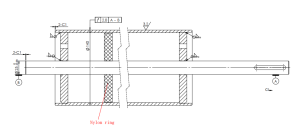
Design considerations:
- The nylon ring diameter should be slightly smaller than the inner diameter of the roller tube, a clearance fit so the ring can float slightly
- This ensures smooth installation without excessive force
Advantages:
- Limits the shaft’s up-and-down swing inside the tube during rotation
- Improves rotational stability
- Nylon material helps absorb vibration and reduce noise compared to metal rings
Potential limitations:
Minor shaft vibration may still exist due to the gravitational deflection characteristics of long-span structures. While dynamic balance is significantly improved, complete elimination of vibration is structurally difficult for extreme lengths.
Solution 2: Dual-Shaft Design (No Central Shaft)
A second solution involved eliminating the long central shaft entirely — a dual-shaft approach also known in the industry as a welded stub-shaft (dead-shaft) design.
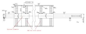
Key features:
- Two short shafts welded at both ends of the roller
- No central shaft through the middle, so there is no long shaft left to bend
Important considerations:
- Welding strength must be sufficient to support the roller load
- Poor welding quality may lead to failure at the welded joints
To improve reliability:
- Two additional sealing plates were added in the middle
- Shaft diameter was increased from Ø25 mm to Ø30 mm. The stub shafts turn in external bearing housings mounted on the conveyor frame (not bearings pressed inside the tube), so a larger stub seats in a larger bearing and raises the roller’s overall load capacity, while the thicker section also strengthens the welded joints
By removing the long central shaft, this design solved the shaft-bending problem, while the larger stub shafts and added sealing plates also improved load-bearing.
Comparison of the Two Solutions
| Condition | Recommended Solution |
|---|---|
| Bearings required on both ends | Internal nylon support ring |
| No bearings on both ends | Either solution |
| High demand for rotational stability | Dual-shaft (stub-shaft) design |
In this case, the customer ultimately selected the dual-shaft design, as it provided better overall stability: with no long central shaft to bend, the load is carried by the much stiffer tube between the two end bearings.
Frequently Asked Questions
Why does the shaft inside a long conveyor roller sag in the middle?
The tube carries the conveyed load to the bearings at each end, while the through-shaft mainly positions the assembly. That shaft behaves like a beam supported at both ends, so its own weight bends it downward, and the bending grows sharply as the unsupported span (roller length) increases. In long rollers, self-weight alone can produce measurable mid-span sag even under moderate load. In one of our projects, a Ø25 mm shaft over a 4572 mm length sagged more than 30 mm at mid-span from gravity, with no external load applied.
Does a bigger roller or higher-grade steel fix sag, or do shaft diameter and length dominate?
The levers that matter most for the shaft are span (roller length) and shaft diameter — length dominates because bending rises sharply with span, while a larger shaft diameter raises stiffness. Higher-strength steel helps only within limits: for multi-meter spans, geometry dominates over material, and a stiffer steel cannot fully compensate for an overlong shaft. Excessive deflection is best controlled through shaft dimensions and internal roller structure rather than material choice alone. Tube outer diameter and wall thickness govern the tube’s own stiffness separately.
Intermittent knocking or rubbing noise — is it a bad bearing, or the bent shaft hitting the tube wall?
On a long roller, a bent shaft can vibrate inside the tube and intermittently contact the inner wall, producing irregular, periodic noise that is often mistaken for bearing failure. It is most likely when the tube is small (for example 50 mm or 60 mm), where there is little internal clearance. A useful tell: deflection-contact noise tends to be periodic and tied to rotation, whereas a failing bearing is usually a more continuous grinding. Adding internal clearance, an internal support ring, or a stub-shaft design addresses the deflection case rather than replacing a bearing that may be fine.
How do you stop the through-shaft from rubbing the tube — does an internal support ring work, and what material and fit should it have?
One practical fix is an internal nylon support ring that limits how far the shaft swings during rotation and keeps it off the tube wall. We size the ring slightly smaller than the tube’s inner diameter — a clearance fit — so it floats slightly and installs without forcing. Nylon is preferred over metal because it absorbs vibration and reduces noise. It improves rotational stability and dynamic balance significantly, but for extreme spans some minor vibration can remain, since the shaft’s underlying gravitational deflection is not fully eliminated. The exact ring clearance and material grade for a given size should be set with our engineer.
Through-shaft with a support ring, or a welded dual/stub-shaft design — how do you choose, and how are the welds kept reliable?
Two approaches solve long-roller sag: keep the through-shaft and add an internal nylon support ring, or eliminate the long central shaft with a welded stub-shaft (dead-shaft) design — two short shafts welded at each end, so no long shaft is left to bend and the load is carried by the much stiffer tube between the end bearings. A rough guide from our projects: when bearings are required at both ends, the internal support ring suits; when rotational stability is the priority, the stub-shaft design is preferred; when neither end needs a separate bearing, either can work. For stub-shaft reliability, weld strength must carry the roller load, since poor welds can fail at the joints; in our case we added two sealing plates in the middle and increased the stub shaft from Ø25 mm to Ø30 mm. The stub shafts turn in external bearing housings bolted to the conveyor frame (not bearings pressed inside the tube), so a larger stub seats in a larger bearing and raises load capacity, while the thicker section strengthens the welds. Joint design and weld specification should be confirmed with our engineer for your load.
Conclusion
Overlong conveyor rollers can introduce serious mechanical issues, including reduced load capacity, shaft deflection, vibration, and unstable rotation. Proper engineering solutions—such as internal support structures or alternative shaft designs—are essential to ensure reliable performance.
Selecting the appropriate solution depends on:
- Roller length
- Tube diameter
- Bearing configuration
- Load requirements
Careful design can significantly improve dynamic balance, service life, and operational stability of long conveyor rollers.
Looking for customized conveyor rollers or bulk manufacturing? Visit our conveyor roller manufacturer page for more details.


